Building an Amiga Null Modem Serial Cable
Sometimes a project starts because I have an idea.
This was one of those times.
Sometimes it starts because somebody else has an idea and I somehow end up making the hardware for it.
Yawning Angel got in touch because he was working on a forthcoming video exploring serial communications in AMOS Pro. To do that properly, he needed a cable to connect two Amigas together.
Unfortunately, he didn’t have one.
So naturally, I volunteered to make it.
Fortunately, this is actually a fairly straightforward little project, and it also gave me an excuse to take a closer look at how the Amiga’s serial connection works.
What I Needed
The parts list is refreshingly short:
- A suitable length of cable
- Two 25-pin D-sub female connectors
- A small piece of wire
That’s essentially it.
For tools, I used a set of cable strippers, a screwdriver, a sharp craft knife, cutters and a soldering iron.
For the main cable I used shielded Cat 6e network cable. It’s probably a little overqualified for the job, but the twisted pairs actually lend themselves rather nicely to the crossover wiring needed for a null modem cable.
Preparing the Cable
The first job was to strip back enough of the outer insulation to fit comfortably inside the D-sub connector housing.
Using a sharp craft knife, I carefully cut through the outer insulation until I could feel the blade reaching the shielding underneath. Because of the construction of the cable, it’s actually reasonably difficult to accidentally cut straight through into the signal wires if you take your time.
Once the outer insulation was removed, I pulled back the braided shield and twisted it together at the base.
Cat 6e also has foil shielding around the individual twisted pairs. I didn’t need that for this build, so all of that could be removed, leaving four exposed twisted pairs ready to use.
A Very Quick RS-232 Detour
The serial standard we’re dealing with here is RS-232 (Recommended Standard 232.)
It dates all the way back to 1960 and went on to become the standard serial interface used by an enormous number of computers and peripherals throughout the 8-bit and 16-bit eras.
For this cable, we’re not simply wiring each pin straight through from one connector to the other.
This is a null modem cable, so several of the signals need to be crossed.
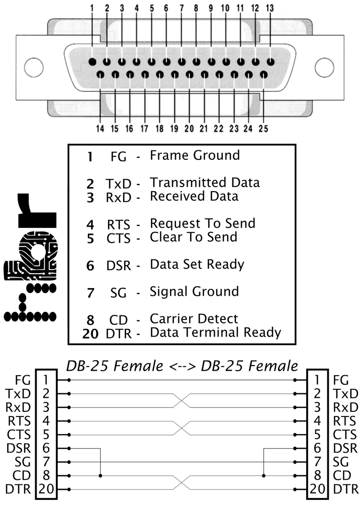
The important connections include transmit data (TxD) and receive data (RxD. Transmit on one machine connects to receive on the other, and vice versa.
The hardware handshaking lines are treated in a similar way, with Request To Send (RTS) and Clear To Send (CTS) crossed between the two ends.
Carrier Detect (CD) and Data Terminal Ready (DTR) are also part of the crossover wiring.
Frame Ground (FG) and Signal Ground (SG) are connected straight through, this should never be joined together.
There’s then one additional connection that is particularly useful for the Amiga: Data Set Ready (DSR) is linked across to Carrier Detect (CD).
That last connection is important because not every off-the-shelf null modem cable includes it. It’s quite possible to buy a cable that looks completely suitable, only to find that you then need to modify it before the Amiga’s serial hardware behaves as expected.
Finding the Pins
One useful feature of the D-sub connectors I was using is that the pin numbers are actually moulded into the plastic around the contacts.
They’re absolutely tiny and not particularly easy to see with the naked eye, but under magnification they become perfectly readable.
I tend to mark pin one with a Sharpie before I start soldering. It’s a simple thing, but it removes a lot of opportunities for confusion once you have a collection of wires hanging off the back of the connector.
Wiring the Cable
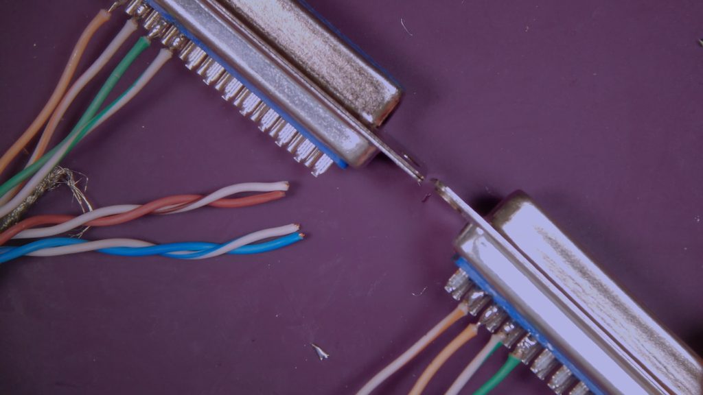
My approach was to wire the cable one twisted pair at a time.
Because Cat 6e already groups the wires into pairs, it makes keeping track of the crossover signals surprisingly convenient.
I also used a simple colour convention.
On one connector I used the solid colour first followed by the striped wire. On the opposite connector I reversed that arrangement.
That way, if anything turned out not to work, I could visually inspect the two connectors and immediately see whether the wiring had actually crossed over as intended.
It’s also worth keeping the soldering iron temperature under control here.
The plastic around D-sub contacts doesn’t particularly appreciate being cooked, so a temperature-controlled soldering iron makes life considerably easier.
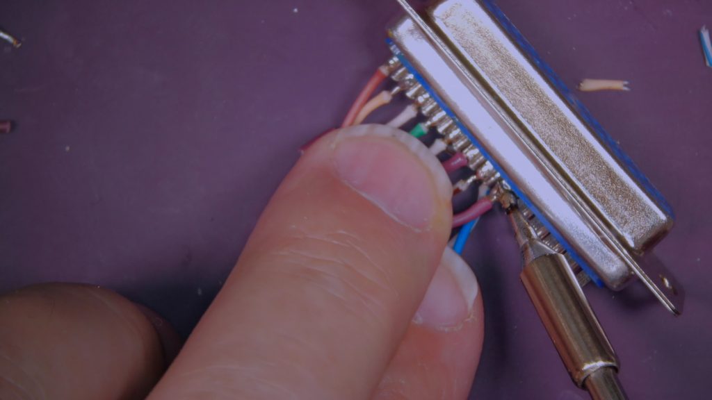
Working through the connections one by one eventually leaves you with 8 wired connections.
The Extra Handshake Link
Once the main wiring was complete, there was one final electrical job.
At each connector I added a short wire between pins 6 and 8, linking Data Set Ready and Carrier Detect.
The reason for this is essentially to convince the operating system or serial driver that there is an active modem connected.
Traditionally, Carrier Detect would indicate that a modem had established a connection over the phone line. By linking these signals locally, the Amiga sees the state it expects without there actually being a modem involved.
It’s one of those little details that can make the difference between a serial cable that mostly works and one that works properly.
The Amiga Serial Port Has Audio?!
While looking through the Amiga hardware information, I also came across one of the stranger features of its serial port.
There are audio connections on it.
One of the pins carries left audio output, and there is also an audio input.
There isn’t a corresponding right audio output.
This apparently wasn’t just Commodore randomly discovering that they had a spare pin and deciding to put some audio on it.
The idea was that, with a suitable modem, the Amiga could effectively function as an answering machine.
It could send audio out through the modem to the person on the other end of the telephone line, while incoming audio could be mixed back into what the Amiga user was hearing.
I’m not aware of much hardware that actually made use of this, but it is exactly the sort of wonderfully odd feature you occasionally discover when digging through Amiga hardware documentation.
In theory, your Amiga could answer the phone.
Assembling the Connectors
With all the soldering completed, I could finally assemble the connector housings.
I folded the cable’s braided shielding back over the outer insulation and clamped it beneath the metal strain relief.
My main reason for doing this was mechanical. It gives the strain relief something substantial to grip and reduces the chances of movement in the cable being transferred directly to the solder joints.
If you want the shielding electrically connected to the connector frame, you can also run a small fly lead from the strain relief to the metal shell of the socket.
I soldered this near the outer edge so it wouldn’t interfere with the plastic housing when everything was screwed together.
Then it was simply a case of repeating the entire process for the other end.
Does It Work?
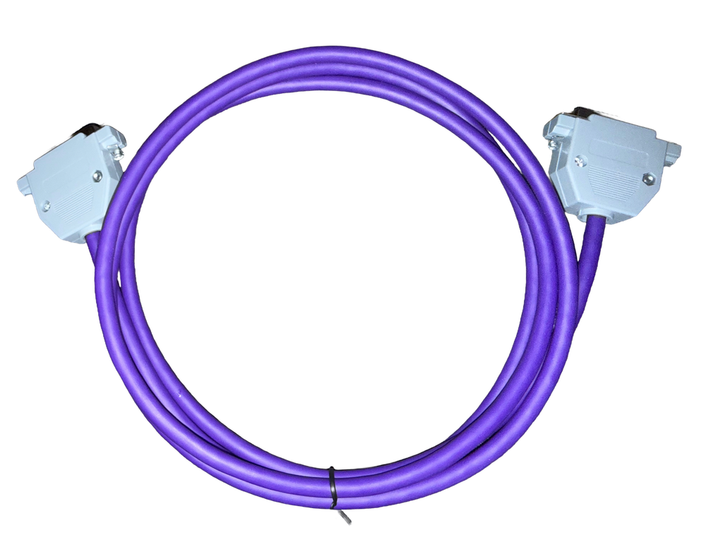
Once both connector housings were screwed together, that was it.
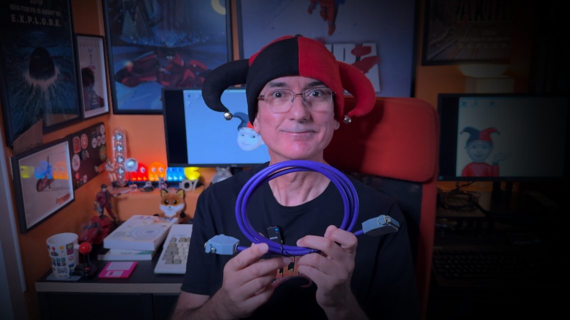
One completed Amiga null modem serial cable.
Of course, the only sensible way to test a cable designed to connect two Amigas together is to find two Amigas and plug them into each other.
So Yawning Angel can do the final testing for his AMOS Pro serial communications experiments, and I got a small project out of it along with an excuse to disappear down yet another Amiga hardware rabbit hole.
https://www.youtube.com/watch?v=mrGvKXgpVhg
Not a bad result for a piece of cable and two plugs!
