My Journey to Build a Fully Functional Amiga 500 Plus in a Mini-ITX Case (and Survive the Battery Damage, Fake STM32s, and 2000 Angry Sockets)
There are two kinds of retro builds: the ones where everything just clicks into place, and the ones where you spend hours soldering your way into a functional Amiga… only to discover you put a SIM socket in backwards. Ask me how I know. In this post, I’m taking you along my hands-on journey to build a fully functional Amiga 500 Plus using a dense Denise board in a mini-ITX case—including the keyboard/PS2 “modern comfort” upgrades, the FlashFloppy GOTEK stack, the joystick/drive mods, and the hilarious-but-educational detours caused by mistakes, tight tolerances, and a small army of sockets.
Starting Point: “This Isn’t a Raspberry Pi” (It’s a Denise in Mini-ITX Clothing)
What I was building wasn’t a Raspberry Pi or an FPGA recreation. It was a fully-fledged Amiga 500 in a mini-ITX form factor. I began with the Denise PCB, supplied by Flame’s Derek—thankfully already populated with the surface-mount components, which turned a potentially week-long slog into something I could actually finish before the universe got bored of me.
What the Denise kit gave me (and what I still had to add)
The Denise board came with:
- 72-pin SIM board included in the kit
- Two pre-programmed chips: one for the “condensed glue logic” and one microcontroller for keyboard/mouse and ROM switching
- Plus modern comforts beyond a straight recreation: PS2 keyboard/mouse support and two Zorro II slots
I also had an Amiga 500 Plus that had suffered considerable battery damage. On the surface it didn’t look too bad, but every attempt to repair it uncovered more damage—and cleaning it properly spread across the whole board was simply too time-consuming. Since I already owned a working Amiga 500 Plus, I decided to redirect the effort: build a new machine rather than wrestle the old one into submission.
My Denise Build Plan (Sorted Boxes, Cautious Optimism)
Denise is densely packed, and I mean “through-hole components crammed like a 90s train commute” densely. Because everything needed its place, I sorted components into separate boxes and followed the build instructions—plus advice from “Cathas” on Discord (who had built several of these boards before).
The order I chose
I installed things in this sequence:
- Resistor packs
- Through-hole resistors and diodes
- Sockets
- Then the rest of the components
Socketing, Heat, and the “Don’t Socket These” Lesson
I will admit I counted sockets like a gremlin counting shiny coins. But there were a couple of chips the instructions said not to socket. The reason given was about timing—specifically something related to RAM access, based on the chip types. I chose to trust the board’s creator. Who am I to argue with the person who designed Denise?
First Boot: The Amiga Worked… After I Fixed My Biggest Mistake
By this point, soldering to get everything at least physically installed took me about 5 and a half hours. After that, it was time for the custom chips and the crystal.
I spent time trying to get the SIM working, and I initially concluded it must be incompatible. In other words: I blamed the hardware. Classic me.
Then I realized what actually happened: I had installed the 72-pin SIM socket the wrong way round. Fixing it required unsoldering and carefully reinstalling the socket—taking meticulous care not to damage the PCB—then testing improved dramatically.
When the Amiga sprung to life after hours of building, the relief was real. It booted, but I couldn’t do deeper tests until I connected a keyboard.
Keyboard + RAM check
With an Amiga test kit, I confirmed the keyboard was functional and that all RAM was working. Everything important was alive.
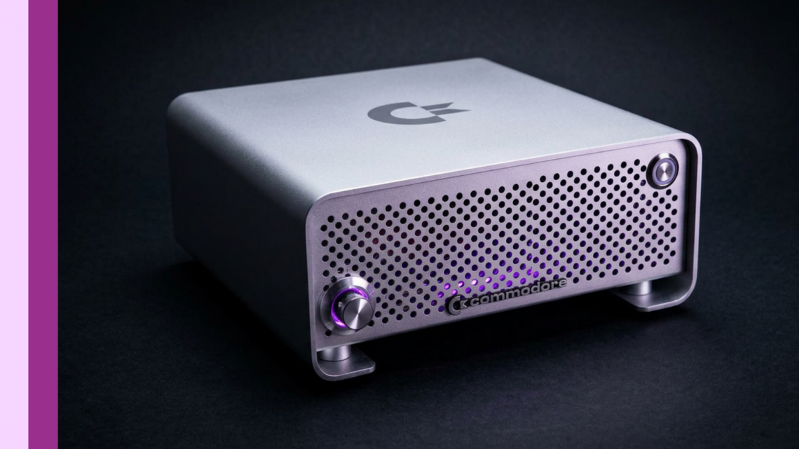
Case Choice: Does Denise Fit in a Standard Mini-ITX Case?
I chose a metal mini-ITX case (described as a solid aluminum case with a kind of Apple Mac-esque finish). The big question people ask is: does it fit?
Yes. Denise fits in a standard mini-ITX case, and that blew my mind given how small the board is compared to the original Amiga 500 Plus PCB.
But there was a glaring omission: no provision for a floppy drive. I knew I would need to modify the case to solve that later.
FlashFloppy GOTEK in a Green-Channel Overlay Dream
To get a display while installing GOTEK stuff, I didn’t want some ugly external box that ruins the case’s clean look. I remembered that old TVs used on-screen display (bright green overlays), and I wondered whether FlashFloppy could do something similar.
Turns out: the creator of Flash Floppy (the firmware I planned for my GOTEK) also has an on-screen display method that overlays generated video onto the Amiga output using an STM32.
What I needed to wire
The STM32 needed two connections:
- Composite sync in
- A video signal back out to overlay on the green channel
I also had to prep the GOTEK board beforehand:
- It didn’t come with the rotary encoder provision, so I had to deal with pins that were filled with solder and install a header
- I removed the LED and replaced that location with a two-pin header for an external LED
- I used a panel-mount USB to keep the outside look clean (drilling a ~21mm hole with a step drill)
The STM32 Plot Twist: Fake “Blue Pill +” and My I2C Pull-Up Error
Programming the STM32 itself was straightforward—until I tried physically connecting it and… nothing happened. I removed the Denise from the equation, tried a stock A500, and still had nothing.
I then ran a blink test using what was described as a “blue pill plus.” It passed with flying colors. So the STM32 was fine—meaning the issue was in my setup.
The next thing I discovered: I had forgotten the two 4.7K pull-ups required for the I²C interface. I ended up installing them in a janky but effective retrospective way, and everything turned out alright.
Then it worked—until I needed the rotary encoder
With everything wired, the Amiga test kit showed up in green loveliness. But I couldn’t change the image yet because the rotary encoder wasn’t installed.
I installed the rotary encoder by wiring it to the rotary encoder header, using right-angle wiring for minimal case protrusion and heat shrink/strain relief techniques for tidy routing. After mounting and wiring, I powered back up and was able to select disk images. Progress!
Cost Breakdown (Because You Asked, and Because I’m the Kind of Person Who Calculates)
I mentioned I wasn’t including the cost of the original Amiga 500 Plus (because I genuinely already owned it when I started). Here’s what I reported for the Denise build parts in UK pricing:
- Denise kit: £120 (from Flame Lily)
- “Bomb” components split between DigiKey and Mouser: DigiKey £69.91; Mouser £46
- STM32: £3.00
- USB mount: £9.44
- LED filaments: £2 (pounds for the front power supply/related LED elements)
- Pico ATX power supply: £9.50
- Case: £45.35
- Other parts: ~£50.00 (parts I already had)
- GOTEK: about £10–£11 (Amazon pricing varied)
Total reported: roughly £366 (again, not including the Amiga 500 Plus itself). I also noted that if someone already has an Amiga 500 Plus, going the Denise route could save roughly £266 compared to buying a prebuilt setup—though I cautioned that costs vary by region due to exchange rates and changing prices.
Joystick Build: Because a Machine Without One Is Just a Fancy Paperweight
After Denise was complete, there was one missing piece: a joystick that matched the aesthetic. I built one into a project enclosure using parts sourced largely from AliExpress/Temu.
The process included drilling the mounting holes and joystick/button apertures (not always as easily as I expected), dealing with step drill limitations, and switching to a hole saw for the button openings. I also had to modify the joystick PCB alignment, repaint the top with leftover paint (sparky black earlier; later a more purple/industrial top), and do final wiring.
Result: the joystick works, the build feels industrial and usable at events like Retrofest, and the top ended up less boring than the original plan. Retro wins again.
Upgrades: Terrible Fire Accelerator + Hard Drive + Zorro Network (and More Mistakes)
Next came acceleration and storage. I planned to add:
- Terrible Fire accelerator
- a genuine spinning-rust 44-pin mechanical hard drive (new old stock)
- a network card (installed via Zorro II slot)
Terrible Fire removal tip
One helpful tip I shared was how to remove Terrible Fire cards: don’t wiggle, don’t pry—use a simple Velcro strap and pull it out evenly in one tug. (I didn’t film the original installation, but I showed this part.)
Hard drive tested before final assembly
I loosely assembled Denise and tested the hard drive before adding all screws. Installing AmigaOS and verifying it worked was successful. When doing a test fit, the rotary encoder cable had wiggled loose again, so I soldered it back on—because tiny case tolerances love causing tiny disasters.
Initial performance observations
I noted RAM speed seemed about three times that of an Amiga 600, and with Terrible Fire’s fast RAM, it might even be more performant than an Amiga 2000—though I framed it as an observation from testing, not a lab-grade benchmark.
Network Riser Saga: Wrong Footprint, Then Right Height
Here’s where my build turned into a comedy of errors… with engineering.
When I tried to install the network card, it wouldn’t fit in the normal Zorro II position because it would stand too high for the tiny case.
My solution: create a custom folded riser that lets the card fold over the Terrible Fire at 90°.
I designed the riser in KiCad and sent Gerbers to PCBWay. The first produced batch had the entirely wrong footprint. Still, I forced a test fit by bending pins, soldering well enough to confirm the concept worked.
Then I fixed the height requirement. After accounting for extra plastic from IDE cable routing, I adjusted the riser by 1.3mm higher. PCBWay agreed to produce corrected cards, which arrived later and made testing possible.
GOTEK vs Floppy Cable vs Network Card: Custom GOTEK Required
Test fitting revealed a new problem: the floppy drive cable would end up over the network card, which wasn’t ideal. Even worse, the case space where I wanted to place GOTEK overlapped with where the network card needs to be.
Given how tight the case tolerances were, relocating GOTEK wasn’t really an option. So my crazy solution was: build a custom GOTEK designed specifically for Denise and the case requirements, fitting neatly onto the floppy drive connector.
I reverse-engineered existing GOTEK boards I had, used rough schematics, and designed the PCB to fit in the available space. I then sent the Gerbers off again and waited for the new boards to arrive alongside the riser revision.
Custom GOTEK Debugging: Fake USB Signaling and Wrong I2C Pins
When flashing firmware the first time, the device didn’t show up on the USB bus. I dug into schematics and found I’d installed 1k resistors on the USB data lines when they should have been 22 ohms. With 1k, it was basically removing signaling so the PC couldn’t detect it.
After correcting that resistor mistake, the controller was detected and flash firmware could be applied.
Then I hit a second problem: connecting a 7-segment display gave random outputs instead of the expected “FF” pattern. Comparing the custom board to the original revealed my I²C bus pins were wired to the wrong microcontroller pins. I fixed it by severing the wrong trace and adding a bodge wire.
After that, the display showed “FF,” meaning the firmware was installed and communicating. Then I tested with an Amiga 500 Plus (not Denise initially) and discovered a schematic label mistake: one select signal label was missing the active low prefix. That meant the select active high/active low weren’t connected correctly.
Again, I fixed it with a bodge wire and then the GOTEK worked inside the Amiga 500 Plus—able to display images and read files from USB through the floppy emulation approach.
Final Big Picture: Denise + Terrible Fire + GOTEK + Network Worked Together
With that debugging done, it was time to test the whole “stack of cards” inside the Denise:
- Install Terrible Fire, GOTEK, and network card together
- Boot into Workbench
- Verify floppies appear on the desktop
- Run CI info from floppy images
According to my testing, it worked: both hard drive positions showed up, the floppy drive was present, hard drive speed seemed unaffected, and RAM configuration looked correct (including 64MB provided by Terrible Fire and 2MB chip RAM).
So yes: the “this should be a simple problem” plan aged about as well as milk in a toaster. But the end result was functional.
What’s Next (Still Tight, Still Learning)
Even after getting everything working together, I still had outstanding issues:
- I broke the rotary encoder again due to flimsy wiring during board removal—so I needed a better mounting/cabling solution while keeping the form factor small.
- The STM32 mounted on a board in the case bottom wasn’t ideal—so I wanted to explore a better internal mounting position to make future installs/uninstalls easier.
I aimed to finish those changes before an event (Amiga Belfast) so the Denise could get its first outing in the improved setup.
Takeaway: Retro Builds Are 50% Electronics and 50% Patience (Plus Erasers)
If I learned anything from this Denise journey, it’s that mistakes aren’t failures—they’re part of the build. A reversed SIM socket, forgotten pull-ups, wrong resistors, incorrect I²C pin connections, and a riser with the wrong footprint all happened. I fixed them one by one, kept testing on real hardware, and slowly got to a fully functional Amiga 500 Plus setup in a mini-ITX case.
And honestly? The moment it boots—especially after it fought back so hard—still never gets old.
