-
My Journey to Build a Fully Functional Amiga 500 Plus in a Mini-ITX Case (and Survive the Battery Damage, Fake STM32s, and 2000 Angry Sockets)
There are two kinds of retro builds: the ones where everything just clicks into place, and the ones where you spend hours soldering your way into a functional Amiga… only to discover you put a SIM socket in backwards. Ask me how I know. In this post, I’m taking you along my hands-on journey to build a fully functional Amiga 500 Plus using a dense Denise board in a mini-ITX case—including the keyboard/PS2 “modern comfort” upgrades, the FlashFloppy GOTEK stack, the joystick/drive mods, and the hilarious-but-educational detours caused by mistakes, tight tolerances, and a small army of sockets. Watch the video on YouTube Starting Point: “This Isn’t a Raspberry Pi”…
-
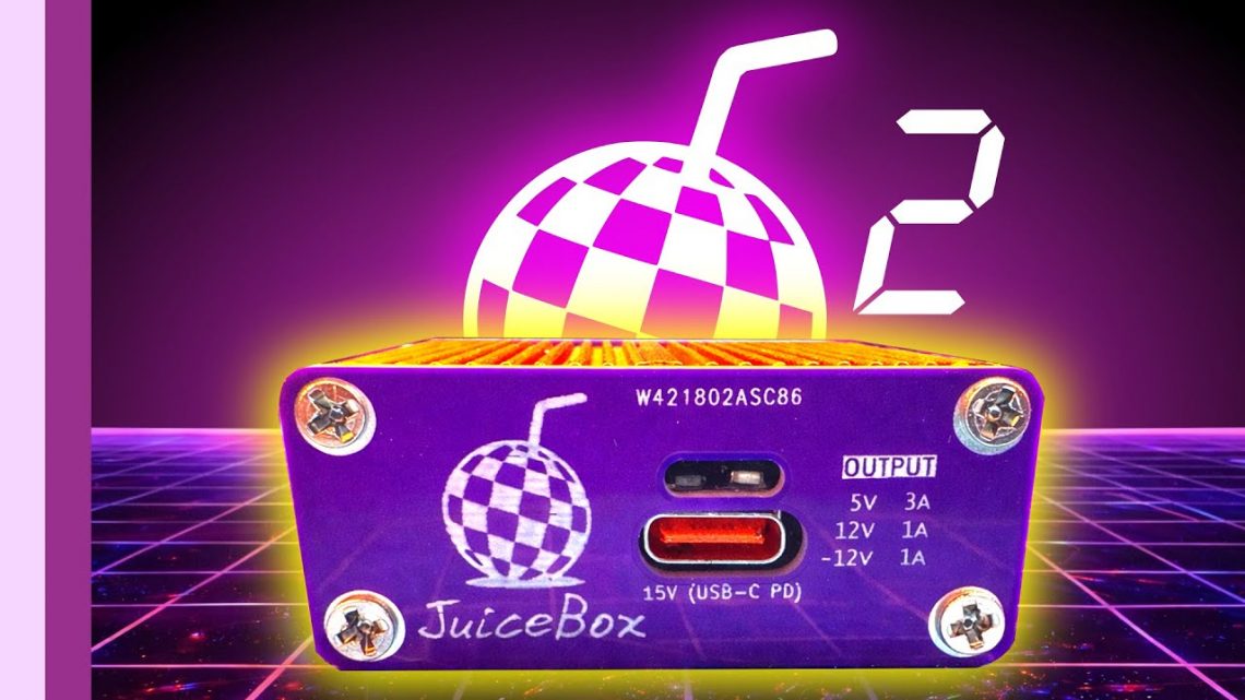
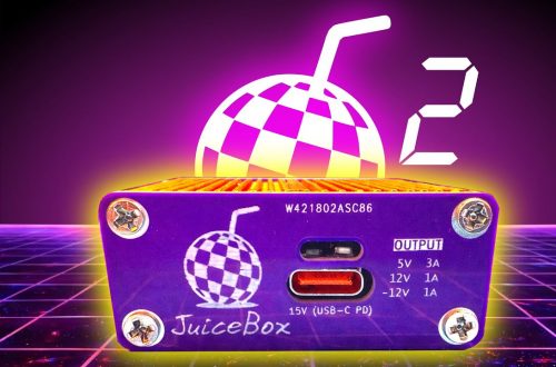
JuiceBox: From Purple PCB to an Upgraded Power Supply (Amiga USB-C Power, Revision 2)
There’s a special kind of nostalgia that kicks in when you’re powering an old computer with modern bits. It’s half engineering, half archaeology—like digging up a treasure chest but realizing it’s full of capacitors and optimism. In my JuiceBox series, I set out to make a compact, USB-C-powered supply for an Amiga—starting with a purple PCB in an orange case, then pushing it through real-world use, teardown nerves, and finally an upgrade to make everything tidier (and calmer) in revision 2. watch it here Chapter 1: The Orange Case Dream (and the Purple PCB that Made It Happen) Before the JuiceBox had a name and a case, I’d already been…
-
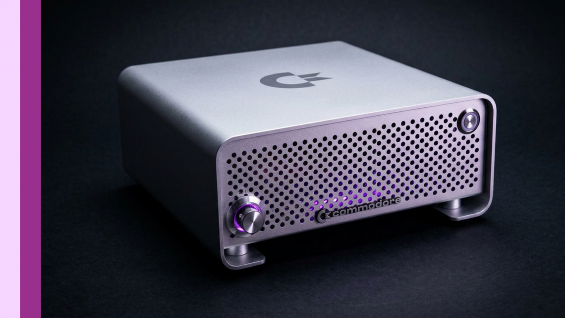
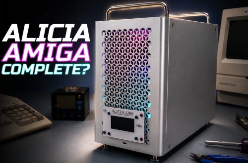
Alicia Build: Resurrecting an Amiga 1200 into a Mini-ITX “Mac Pro”-Style New Home
I didn’t set out to build “another retro computer.” I set out to resurrect an Amiga 1200 in a different form factor—only to discover, as always, that the past has a way of handing you extra homework. That’s the ethos behind my “Alicia” series: journeying forward into the future while journeying back to remember the past and learn from its lessons. In other words: yes, we’re making something tiny and powerful… but we’re also documenting the dents, the detours, and the surprisingly educational moments along the way. watch the Alicia build complete—Part 1 here Chapter 1: Resurrecting the Amiga… into an Alicia When I started this Alicia project, it really…
-
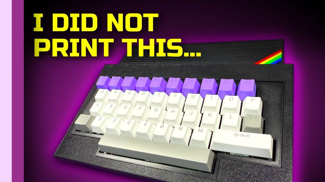
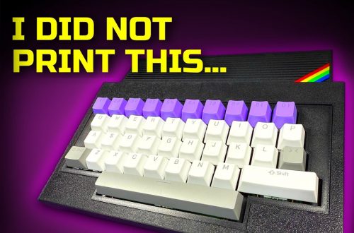
How I Built a 2025-Ready ZX Spectrum Keyboard Case Without a 3D Printer (PCBWay to the Rescue)
There’s a special kind of retro tragedy that happens when you’re ready to print, paint, and perfect your next ZX project… and then your 3D printer doesn’t survive the move. I hit that exact wall recently—right before retro stuff became the plan—so I had to ask myself: can I still build a brand-new Spectrum-style case in 2025 without doing the “3D printer hobbyist” thing? Turns out, yes… and it involved a sponsor, a material choice, and a level of paperwork I didn’t know existed. Also: I may have invented a packing-foam soldering jig. Let’s rewind and walk through exactly what I did. Watch the video on YouTube Why I Didn’t…
-
I Upgraded My Amiga’s Power Connector with a Magnetic USB‑C Style Hack (and a Few Soldering Gremlins)
This started as a simple “what if?” after I noticed my MacBook Pro’s magnetic power connector. You know the feeling: no fumbling, no wiggling, just click—and the power’s connected. Naturally, I thought, “Could an Amiga get the same quality-of-life glow-up?” And because retro projects are basically 50% engineering and 50% accidental slapstick, I also decided it would be fun to find out whether it was even possible. Watch the video on YouTube The Juice Box: the power supply I didn’t expect to love this much Before I touch the magnetic connector itself, I need to set the stage: my “Juice Box” power supply has been a bigger success than I…
-
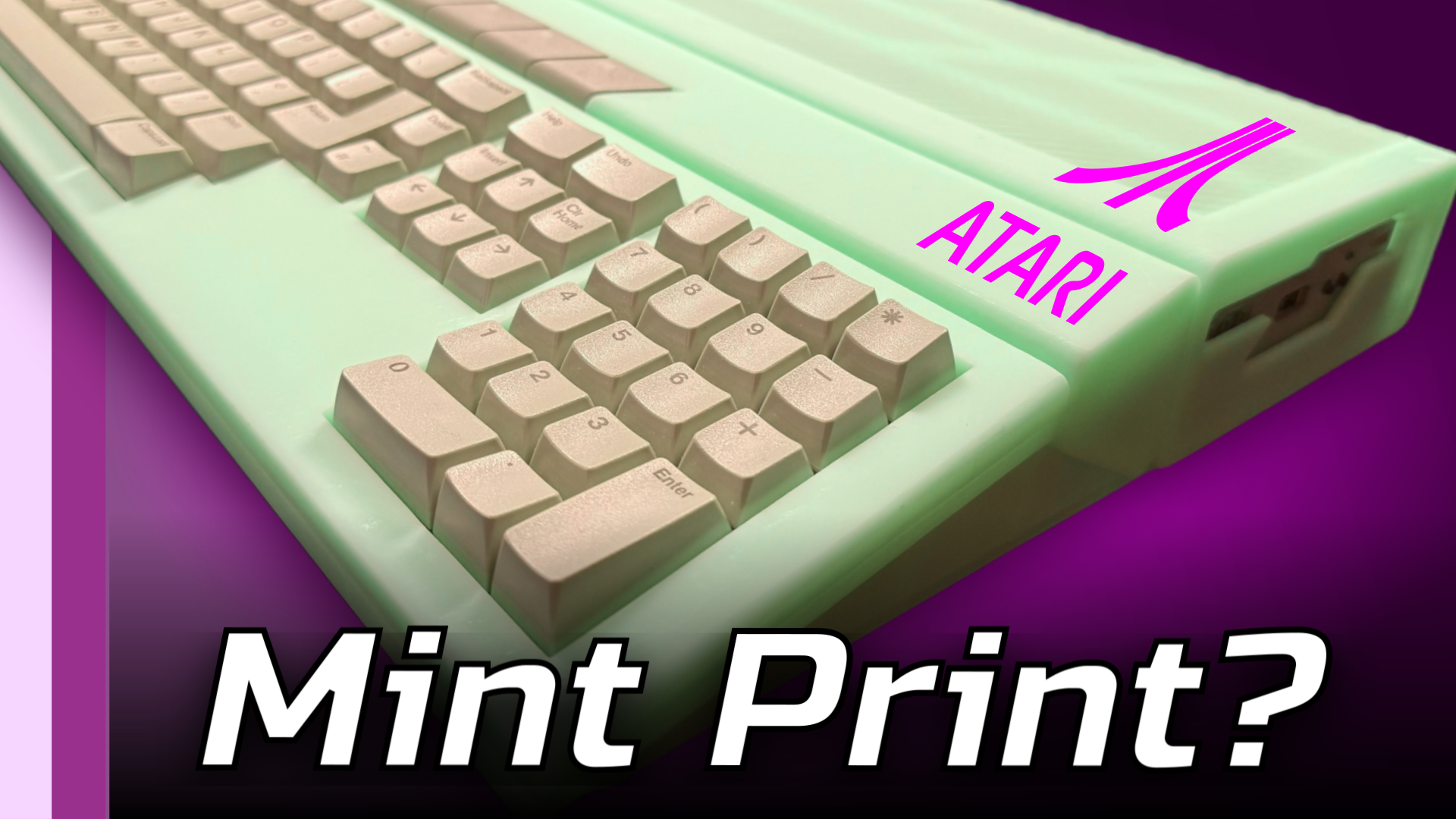
Breathing New Life into My Atari ST with a 3D Printed Case
For years, I’ve watched aftermarket case projects flourish for the Amiga 500 and 1200 — sleek, modern, injection-molded shells that let aging systems shine again. But the Atari ST? It’s been sadly left behind. If you’ve ever owned one, you’ll know the ST’s case plastics are incredibly brittle, and time hasn’t been kind. So I asked myself: why not 3D print a new one? Thanks to the good folks at PCBWay, who kindly sponsored this build, I got to put that idea to the test. The Case for a New Case When the box from PCBWay arrived, I couldn’t wait to tear it open. Inside was something I’d never seen…
-
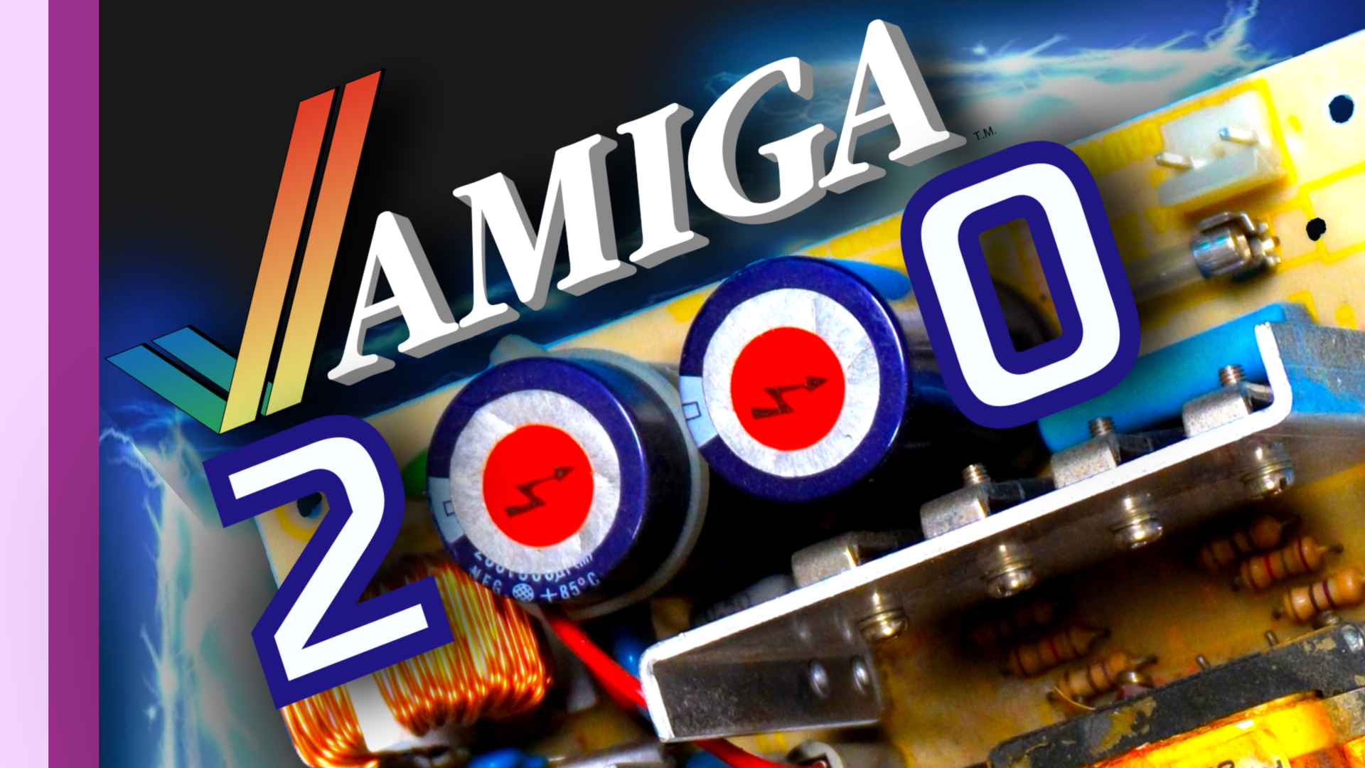
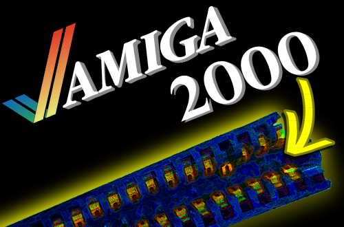
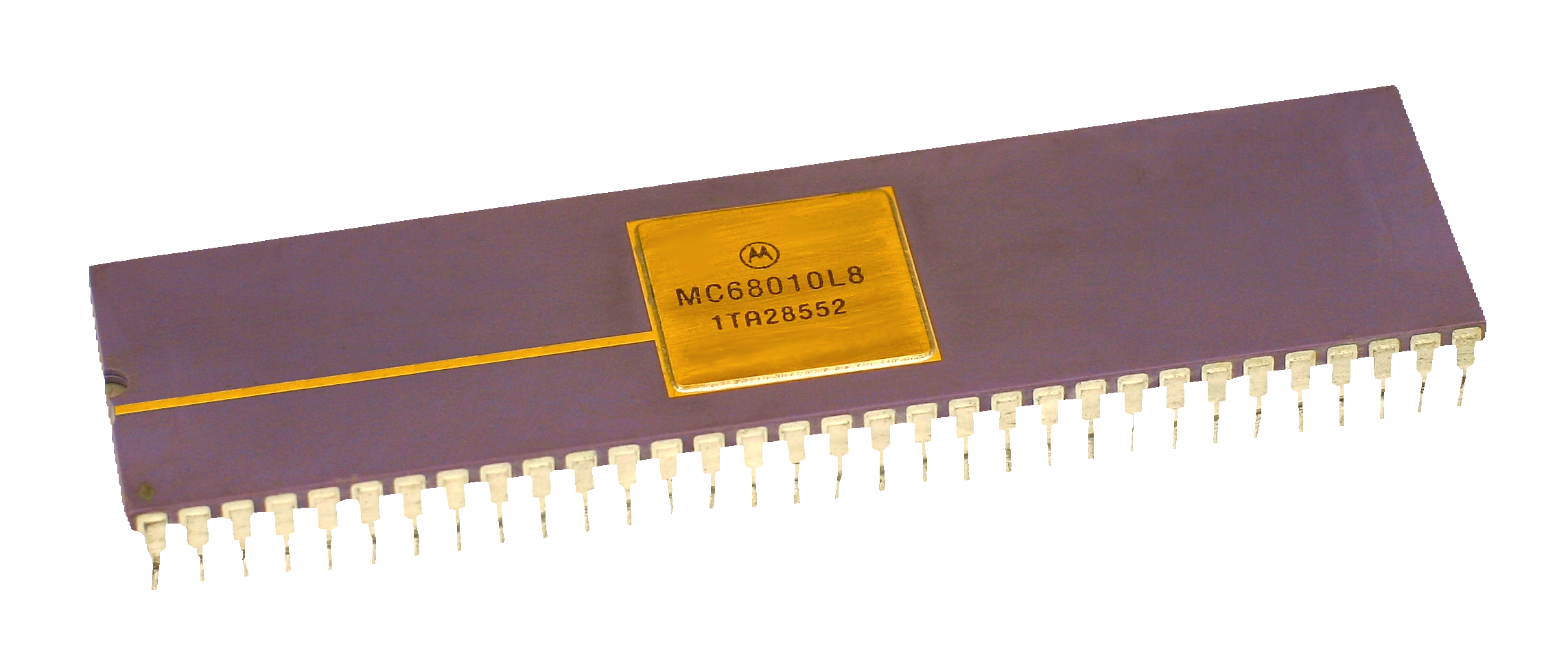
The Curious Case of the ETX Amiga 2000: A Debugging Odyssey
What you see on the bench now is a working ETX-form Amiga 2000—but to understand how we got here, we need to rewind a bit. This strange little tale really begins when I picked up the board from Cathers in Cambridge. The First Setup Fresh back from Cambridge, I wired it up with a ROM switcher—technically meant for an A600. Not the perfect fit, I’ll admit, but it had all the Kickstart images I needed to investigate the problem for myself. That issue? Something was seriously wrong with the display—especially under Kickstart 2.0 or higher. The colors were just… off. Glitching, corruption, odd effects during animation. It was like looking…
-
A600 Upgrades Continue
After completing the restoration of my Amiga 600, I found myself craving a deeper challenge. Sure, I could’ve gone all out with accelerators and high-end mods, but that’s expensive, and honestly, I wasn’t looking for overkill. What I really wanted was a compact machine that stayed true to its roots while still offering a touch of modern convenience—perfect for playing classic games. Aesthetic Masterpiece Externally, the A600 is now a thing of beauty. It’s got a two-tone paint job with a gunmetal gray top and a pearlescent candy orange bottom. If I’m being honest, it’s probably one of the nicest case customizations I’ve ever done. But as striking as it…
-
I had to do something…
To view this content, you must be a member of Andi's Patreon at $1 or more Unlock with PatreonAlready a qualifying Patreon member? Refresh to access this content.
-
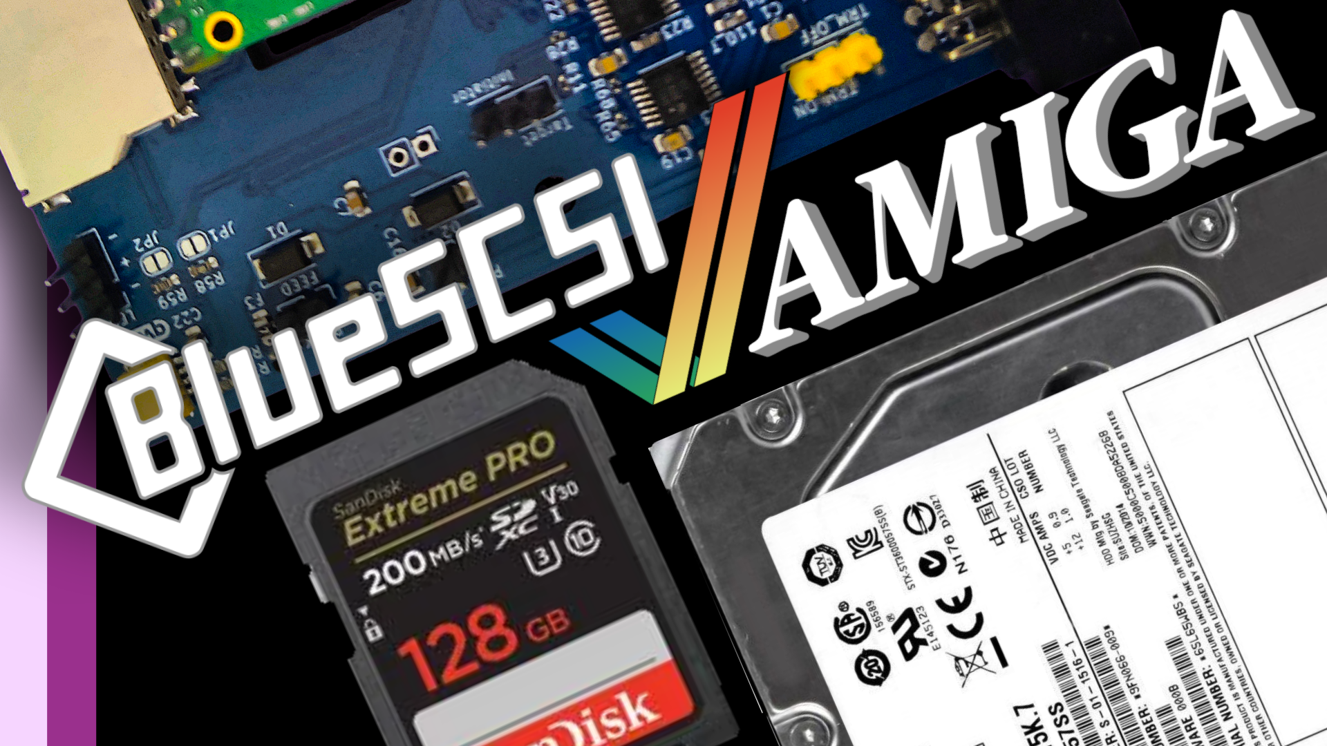
BlueSCSI Setup for Adaptec EZ-SCSI 4 in DOS
https://www.youtube.com/watch?v=4k1i_IFYy0U Building a Retro PC with BlueSCSI: My Journey Hi everyone! I wanted to share my recent adventure in building a retro PC setup, complete with a BlueSCSI for storage emulation. What started as a simple idea turned into a learning experience filled with challenges, unexpected twists, and ultimately, a lot of satisfaction The Vision I’ve always had a soft spot for old-school PCs. After scratching my nostalgia itch with an IBM 5170, I set my sights on building a DOS gaming machine—something to relive the magic of Doom and Quake. For this build, I used a Baby AT motherboard. While most had transitioned to ATX by the time my…