Building a Frankenstein Amiga: A Journey of Restoration and Customisation

Today, I’m diving into another exciting project: creating a Frankenstein Amiga from various parts I have lying around. Most of these parts come from a job lot of leftover spares I found on eBay. You might be wondering why I’m doing this. Well, I’m challenging myself and also building an Amiga for a charity auction organized by a friendly man named Lee from the YouTube channel More Fun Making It.

The Challenge Begins

There’s something a little strange going on with this Amiga 500 Revision 5. It seems that not all the RAM chips are managing to output TTL logic levels. Based on what I’m seeing on the scope diagram, it’s giving me random green and blue flashes. So, I’m going to pull all the RAM out and socket it. Having the RAM in sockets will be a much better solution for the new owner, especially if any of the RAM I’m installing goes bad in the future.

A Series of Unfortunate Events

The first thing I desolder, ignoring my marks, is the resistor pack. Well, let’s just style that out and pretend no one noticed (lol). Now, all the RAM has been removed, before we can solder in any of the new sockets for the RAM, we need to tack back in those resistor packs—the ones I unsoldered for no reason. Not that I’m planning to put any of the original RAM back in, but let’s go ahead and test it to see if it shows up as bad. Amazingly, all of the RAM tests good. I suppose the heat from desoldering the chips might have revived it, or maybe the logic levels I saw are enough for the tester but not for the Amiga. Or perhaps the RAM isn’t the issue, and we’ve got something else causing the Amiga not to function.

Progress

Time to start putting the sockets in: 16 * 16 pin DIP sockets, that’s 256 solder points plus the resistor packs that I unsoldered for no reason. I tack in one socket and solder it up to make sure I’m happy with the temperatures before I go ahead and install all the rest. I tacked in the rest using the two voltage pins, 5 volts and ground. The followed up by soldering the rest of the pins and clean up the flux. That’s all the sockets installed. Now they just need chips.

Installing the RAM

I remembered someone saying they hated turn pin sockets because they’re hard to line up with the chip pins. So I thought I’d showcase how I do it. This is just how I do it; it’s not advice. I’m not a chip insertion instructor. If you don’t like it, don’t do it. I’m just saying it works for me. Basically I insert one row of pins and then gently apply pressure to the other side while running my tweezers across the chip pins this locates the pins in the socket, it usually takes a couple of strokes for all the pins to align then the chip just goes in without issue. This is similar mechanics to picking a lock…

All the RAM is installed and looking lovely. I took the liberty of fixing the ROM socket so it will take a 27C400 EPROM or a later mask ROM. This is another future-proofing step for the next owner should they want to upgrade to a later Kickstart version.

Final Touches

We have life! I’ve cleaned up the flux and covered the bodge wires from the ROM socket modification. We have a working board, but we need more than that to build a full Amiga. In the same job lot of parts, I have several bits of keyboards. This is where it gets even more Frankenstein. The keys aren’t laid out in the same way as my other 500s. I think this is from an earlier keyboard. The controller is from a Rev 6 Green Power Light. If you can properly identify the original revision any of these parts came from, then please comment on the video.

Testing and Tuning

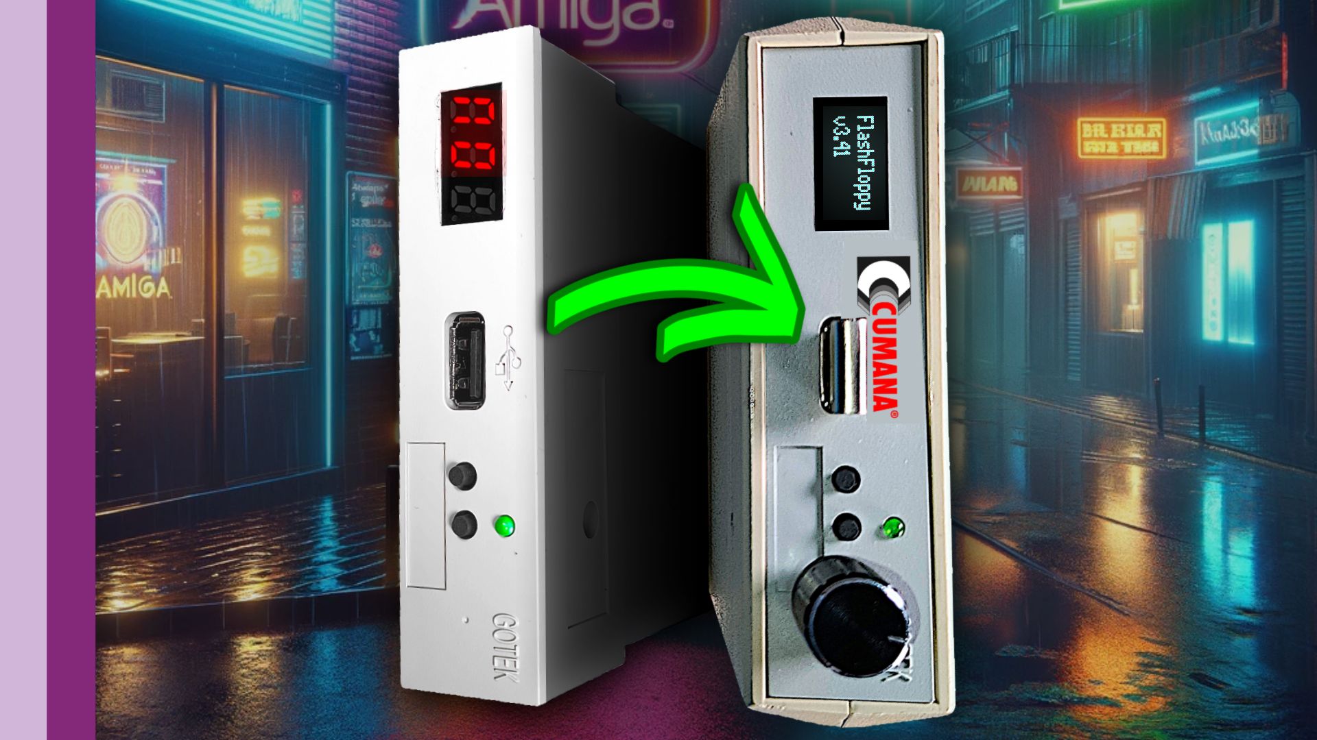
Hooking it all back up with the keyboard and making sure it’s happy before we swap out DiagROM for Kickstart and try booting the Amiga into Test Kit. After confirming all is well with the Amiga, the next step is to get it to boot into Workbench and see if we can load StarTracker from the external GoTek drive. The plan is to load a module and play it, which will give I/O, graphics, and RAM a fairly good workout.

Going the Extra Mile

Since we’ve opened Pandora’s box, I thourght why not see if we can get that 512K of RAM in the trapdoor to be chip RAM? Having a total of 1MB chip RAM opens more games and options for the next owner. We just need an 8372A Agnus some little modifications. JP2 needs to be swapped, we need to cut a trace from Gary to the trapdoor, and we need to cover pin 41 on Agnus to keep it in PAL and prevent it from switching to NTSC.

While you weren’t looking, I’ve sprinkled a little cosmetic customisation over this Amiga 500. All we need now is a case.

Part 2 coming soon!

Building this Frankenstein Amiga has been a labor of love, filled with moments of frustration and triumph. I hope it finds a good home at the charity auction and brings joy to its new owner!

Reviving the Amiga 2000: A Journey of Restoration and Problem-Solving

I’ve taken on the challenging yet rewarding task of bringing an Amiga 2000 back to life. If you’ve been following along, you know the journey hasn’t been smooth. The last update left the Amiga half-assembled with a problematic CPU slot and an overheating hard drive. As if that wasn’t enough, the power supply decided to give up on me.

Upon deeper inspection, it was clear that more work was needed. The power supply was non-functional, leading me to replace a suspect capacitor, though these fixes didn’t solve the problem.

Delving deeper, I decided to replace the voltage comparator and the strobe controller—fortunately, these parts were inexpensive. I installed new sockets and integrated circuits, hoping this would fix the issue.

Despite all these efforts, the power supply still failed. This led me to completely recap it, which seemed promising until it catastrophically failed again after just 15 seconds. I realized that some parts were either unknown or impossible to find.

I obtained a COMPAQ HB 146 SNQ power supply that mirrored the Amiga 2000’s requirements, I decided to adapt an ATX power supply, ensuring it matched the original’s settings. This required making it a permanent 230-volt input and using the original Amiga 2000 switch to activate the ATX’s PS-ON signal, effectively integrating it with the original system.

Testing the new setup, I used an old SCSI hard drive as a load to ensure stable voltage outputs. The results were satisfactory, with the 5V line perfectly on target, although the 12V line was slightly low—a point some might contest.

With the power supply sorted, I turned my attention back to the Amiga itself. I cleaned up acid damage on the board, replaced the battery with a more reliable one, and swapped out the old hard drive bracket for a 3D printed back plate, enhancing the setup.

However, issues persisted. Testing revealed unexplained memory discrepancies, and further investigation showed a short across two address lines on the board—a likely artifact from replacing the CPU slot. After removing the offending sliver of metal, I restored proper functionality to the memory and Zorro boards.

The journey didn’t end there. The Amiga’s ZZ9000 card, used for flicker fixing, lacked a crucial tick signal. I cobbled together a 50 Hz generator using a 555 timer and various components, which not only worked but improved the ZZ9000’s output.

This project has been a testament to the challenges and triumphs of hardware restoration. It’s a continuous learning process, filled with setbacks and victories.

Vintage Vibes: GOTEK Drive’s Nostalgic 80s Upgrade

In my latest quest to enhance my Amiga tech setup without succumbing to the often-inflated prices attached to Amiga-branded tech, I decided to embark on a project that not only tickles my nostalgic senses but also brings modern efficiency to my beloved Amiga setup. I’ve always had a particular disdain for the aesthetically displeasing, modern external floppy drive enclosures that seem to populate the market today. They often come with compromises, such as a lack of the vintage 23-pin D type connectors, essential for that authentic connection, or the absence of a pass-through feature on the back, which I find incredibly useful.

Determined to maintain the vintage aesthetic while upgrading the functionality, I turned to an original external floppy drive enclosure from the glory days of the ’80s and ’90s. The charm of these enclosures isn’t just their look; it’s the functionality they offer – the 23-pin D type connectors, the pass-through capability, and the drive enable/disable feature on the back, all of which are sorely missed in their modern counterparts.

For this project, I chose a CUMANA 3.5-inch floppy drive enclosure, a brand that resonated with my school days, being the provider of all floppy drives during my education. The aim was to convert this enclosure to house a GOTEK floppy emulator, a device that replaces the traditional floppy disk with a USB flash drive, thus bringing the convenience of modern storage to vintage hardware. The GOTEK itself is pretty standard, equipped with a seven-segment display and basic firmware, but perfect for what I had in mind.

The upgrades planned were significant but straightforward: replacing the seven-segment display with an OLED display for better visibility and aesthetics, and adding a rotary encoder for improved navigation and selection of the USB files. The OLED display choice was the compact 0.91-inch version, which fits perfectly without overwhelming the vintage enclosure. The rotary encoder, a simple but effective analog device, adds a tactile navigation method that feels right at home with the Amiga setup.

One of the interesting challenges was ensuring compatibility with the Amiga’s unique floppy disk format. Modern GOTEKs are designed with industrial applications in mind and don’t naturally support the Amiga disk format. However, with the Amiga community being as vibrant and inventive as ever, custom firmware solutions like FlashFloppy have emerged. This firmware enables the GOTEK to read and write Amiga disk formats, effectively mimicking an original Amiga floppy drive.

The actual conversion process involved some soldering and a bit of creative cable management but was overall a rewarding experience. It involved installing a jumper, soldering a right-angled six-pin Dupont header for the rotary encoder, and making minor modifications to the GOTEK’s case to accommodate the OLED display. The end result was a GOTEK emulator that not only fit perfectly within the vintage enclosure but also functioned seamlessly with it, providing a modern solution to a retro problem.

Testing the setup with an Amiga 500 and Kickstart 2.4, I experienced a seamless boot to the Amiga Test Kit, followed by successful loading of Workbench 3.2 from the install disk image. This confirmed the successful integration of modern storage technology into the vintage Amiga ecosystem, all housed within an enclosure that keeps the aesthetic of the era alive.

This project, sponsored by PCBWay, showcases the perfect blend of retro aesthetics and modern functionality. It’s a testament to the enduring legacy of the Amiga and the innovative spirit of its community. For anyone looking to replicate this setup or seeking assistance with similar projects, PCBWay offers comprehensive services from PCB prototyping to assembly, making them an invaluable resource for hobbyists and professionals alike.

In conclusion, this venture into blending old with new has been an immensely satisfying journey. It reinforces the idea that with a bit of creativity and community support, we can preserve the essence of vintage computing while enjoying the conveniences of modern technology.

Cookie Consent Banner by Real Cookie Banner